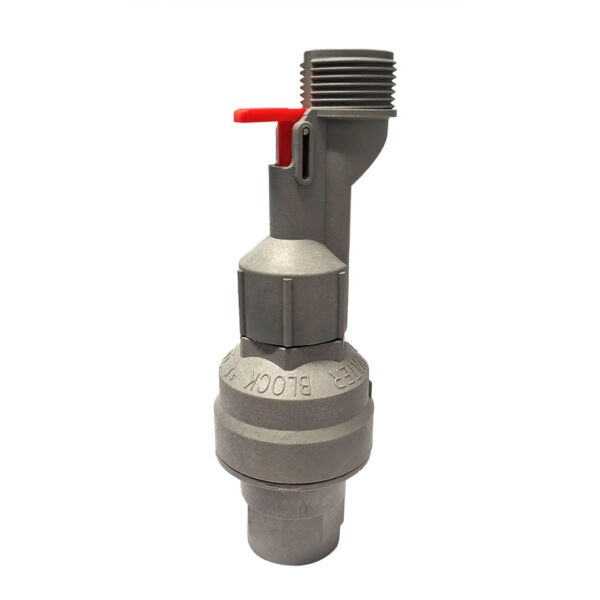
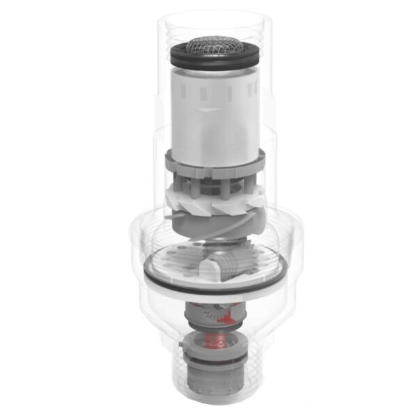
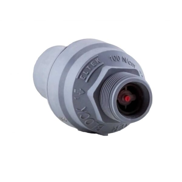
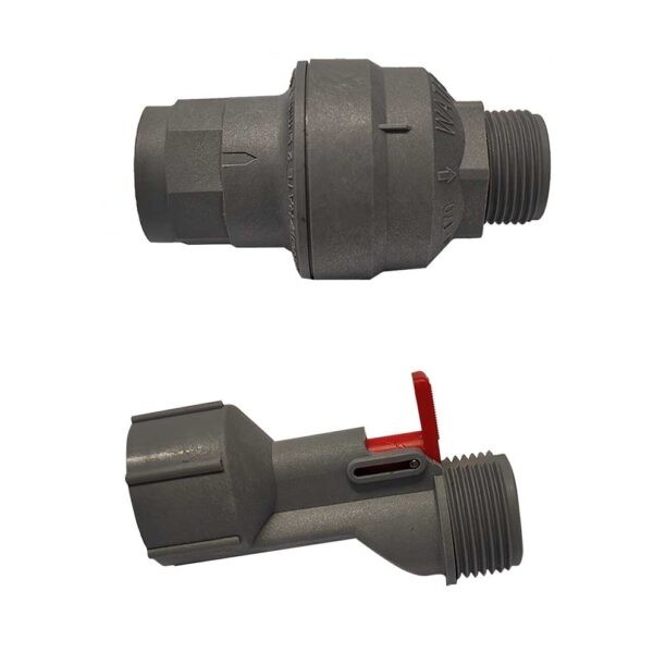
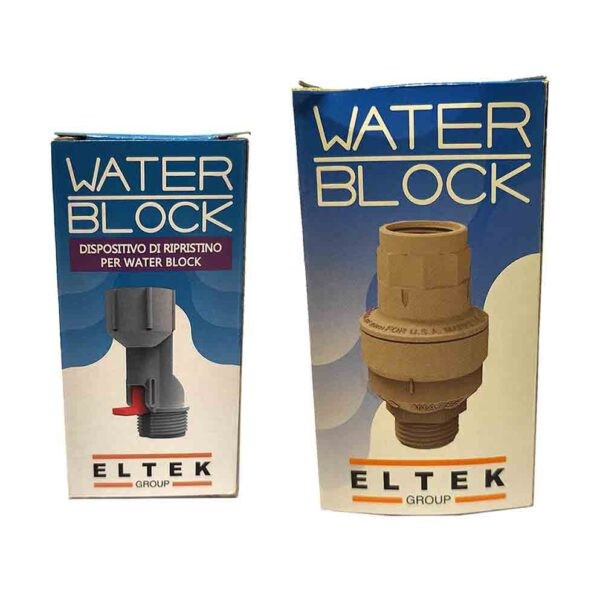
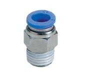
The valve Water Block is a Security instrument anti-flooding used to control the passage of a volume of water between 5 and 50 liters.
Its fuction is to measurement of the passage of the water and if this quantity is more than that fixed.
It stop immediatelly
Ideal for all machines that run with water. treatment systems. osmosis. dishwasher. washing machines.
He does not need energy from outside, because ‘to operate using the stream that flows within it.
Features
- Resistant, environmental conditions limit.
- Resistance to temperature changes.
- Resistance to moisture.
- Resistance to oxidation.
The device counts the quantity of water passed.
The average of the past for each notch of adjustment 4,5 – 5 liters.
Instructions
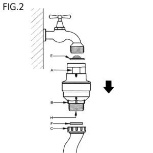
Water Block should be assembled on the tap and the supply pipe of theelectrical appliance (FIG. 2). Using the wrench supplied, rotate indicator P in an anti-clockwise direction until the desired position is reached: for washing machines for domestic use, indicator P should be set on no. 8 (FIG. 1); for application on dishwashers, bring indicator P to no. 4 (Fig. 1).
For ‘use on other appliances regulate the indicator to the position suitable for the type of application, remembering that each number of the scale corresponds to a controlled volume from 4 to 6 litres. In the event of installation on appliances that include the supply of drinking water, it is recommended to let mains water flow at maximum flow rate inside the device for at least 20 minutes before connection, to remove any impurities that could accumulate during storage.

Assembly
1. Screw the WB on manually to the threaded tap (%” gas), inserting filter E with the cover turned upwards as in (FIG.2). Incorrect filter assembly will not allow the WB to work properly; in case of tightening or unscrewing with a tool, use the specific octagonal compartment A.
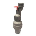
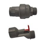
2. Screw the water loading pipe C to the lower part of the WB. If the loading pipe has a filter, the latter must be removed and replaced with a flat seal F; in the event of tightening or unscrewing using a tool, use the specific hexagonal compartment B to block the WB during operation. If there is a fault that produces continuous leaking the WB closes the water flow following passage of a quantity of liquid equal to that previously set on indicator P. To restore functioning of the WB after activating the blockage system, close the water tap and fix the fault; then unscrew the water loading pipe C from the WB and press button H, which is found on the lower part of the appliance (FIG.1). If the pressure of the water inbound is high, this manoeuvre may be difficult. In this case lightly unscrew the WB from the tap: button H can then be easily pressed. Then repeat the operations indicated in the assembly section.

Warnings
To prevent possible damage caused by the water contained in the WB freezing after installation, the room temperature during use must never go below 2°C. All liability is however declined in the event of tampering and/or incorrect use of the WB or its use in applications and/or solutions not expressly planned in these instructions, or rather different and contrasting to them”.
Technical data
- Number notches adjustment: 10
- Increase for each number: 4.5 – 5 liters
- Volume control max: 45 – 50 liters
- Temperature: The water inlet must not exceed 70 °C
- Flow rate: 2 to 30 l / min.
- Power Consumption: does not require electrical connections.
- Pressure: min. 0.2 – max. 10 bar.
- Connection to the pipes: the attacks are female threaded 3 / 4 “input side filter. Male-threaded 3 / 4” output.
- Dimensions: 90mm x 5Ø
In case of block the valve can easily be and quickly reboot with the lever.


