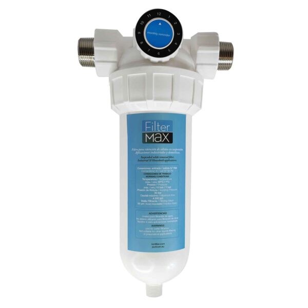
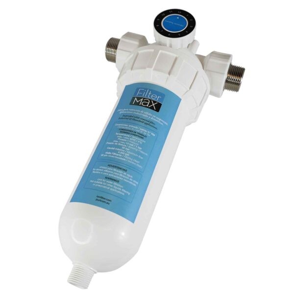
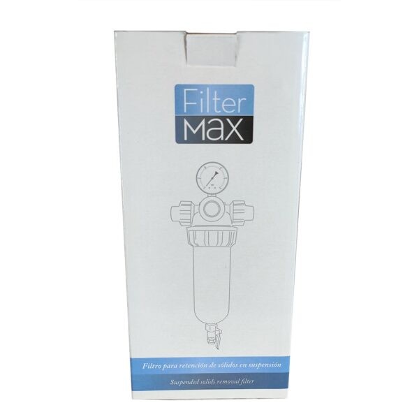
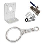
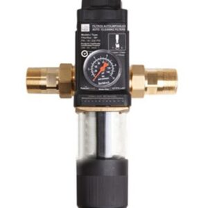
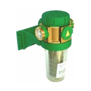
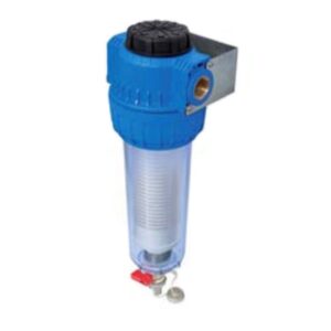
Manually washable filter with 80 micron stainless steel filter mesh. Vertical system installation. Drain valve at the bottom for cleaning at any time.(3/8″ hose, 3/8″ thread).
The installation and use of the filter is subject to the corresponding specific regulations of each country.
The filter uses screen filtration to remove the particles with a coarse or fine particle size, whose size is greater than or equal to the filtering mesh (strainer) of the filter.
Particles that are smaller than the used mesh, the turbidity (i.e. substances making water look turbid) and dissolved substances in water cannot be removed from water via filtration.
This filter is suitable to use in cold drinking water up to a maximum room temperature of 30 °C.
Working limits
– Pressure (max. / min.): 10 / 1.5 bar
– Room temperature (max. / min.): 30°C / 1°C
– Temperature of water to be treated (max. / min.): 40°C / 1°C
– Maximum flow: 4,200 l/h
Technical characteristics
– Connections: Inlet / outlet male thread %”
– Filtering mesh: Stainless Steel 40 microns
– Burst pressure: 30 bar
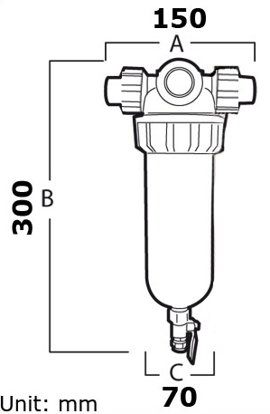
– Dimensions (A x B x C): 150mm x 300mm x 70mm
Technical specifications
– This system has been designed to install in an horizontal pipeline, with the cup in an upright position and a lower rinsing valve.
– Lower rinsing valve with a thread of 3/8”. It allows the connection of a 3/8” tube for the drain.
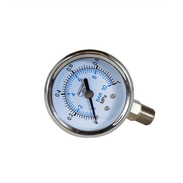
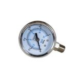
– Upper male connection of 4” for the pressure gauge.
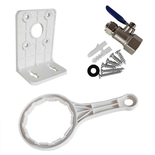
– Wall mounting bracket included.
– Indicator for last cleaning.
Installation
– This equipment must only be installed by qualified technical personnel.
Warning: The room where the unit will be installed must be a dry place without risk of freezing.
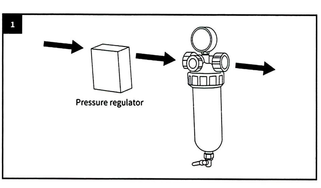
– The water pressure must be within 1.5 bar and 10 bar. If the water pressure is higher than 10 bar, install a pressure regulator before the filter (FIG. 1). Ifthe working pressure is higher than 10 bar, it may cause malfunctions.
– It is recommended to install a pressure regulator if water pressure is within 5 and 10 bar.
– Please keep a minimum space of 200 mm in the upper and lower sides of the filter. Such distances are necessary to be able to carry out the rinsing properly.
– Install a shut-off valve in the upstream ofthe filter to be able to close the water supply during installation, service/maintenance, repair and in the event of a malfunction.
This will prevent floods and serious damages in the house.
– The filter must always be installed in an upright position (+ 5°).
-Screw the huts or fittings of the Installation into the tubes of the filtermax head.
– Observe the dimensions of the installation.
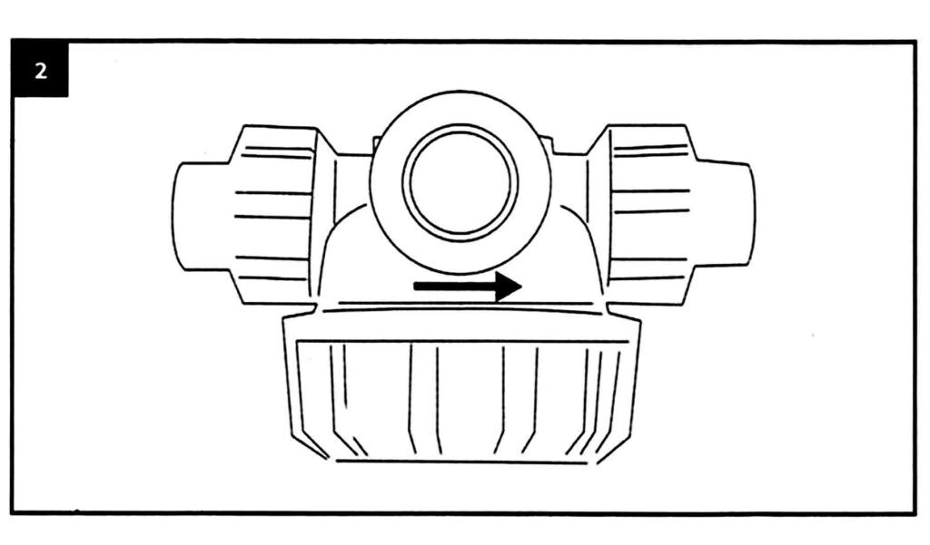
– The arrow of the head must be pointing at the same direction as the circulation direction of water (FIG 2).
Drain
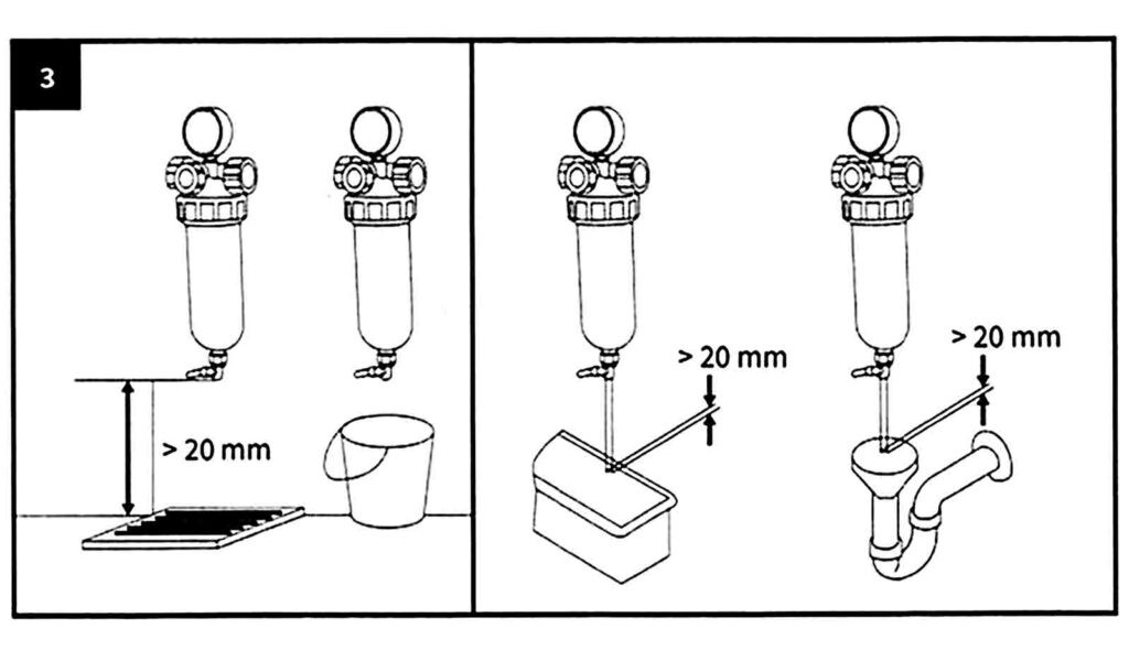
There must be a waste water connection (e.g. a drain on the floor) with the proper dimensions for the rinsing water. If no proper waste water connection is available, a bucket can be used (FIG. 3). The tube must be the same size as the washing water valve.
If the pressure in the main supply valve is too high, water could splash out of the bucket, which would result in property damage in the vicinity of the filter.
When the bucket is half full, stop the rinsing process. Otherwise it might overflow. That is why the bucket must be of the right size (FIG. 3) and the rinsing must be carried out quickly.
Initial Operation
– Before the initial operation of the filter (first start-up or after the maintenance), fill the filter with water and purge it.
– For this purpose, after the installation, fill the filter with water by opening the upstream shut-off valve. Now the filter has the same pressure as the water system.
– Then, remove the air that may have been left inside the filter to prevent any damages in the installation caused by a water hammer.
Description of operation
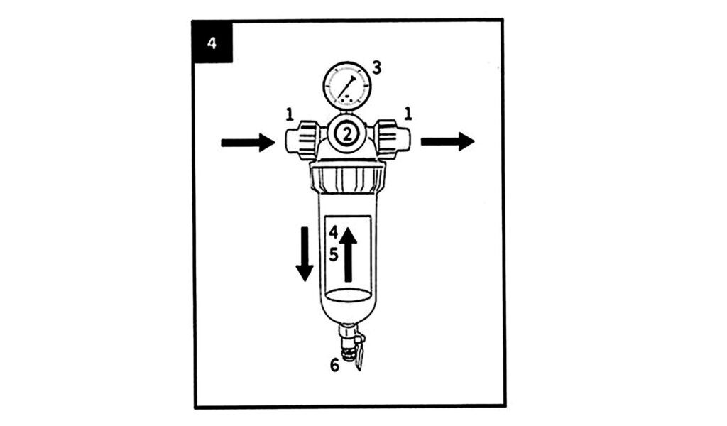
Un filtered water flows through the inlet tube (1) towards the filter. Water goes through the fine filter from the inside towards the outside. The filtered dirt is retained in the fine sieve of the filter (4). Then, filtered water goes out of the filter through the outlet tube (9).
1. Inlet / outlet connections
2. Display button
3. Pressure gauge
4. Mesh
5. Filter housing
6. Purge valve
